Dinghy Dreaming
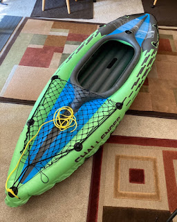
Since my boat search had stalled, I moved on to finding a dinghy, which is admittedly a backwards, unconventional and even heretical way of thinking; putting the cart before the horse, you might say. I love the idea of a RIB with its hard-shell bottom and reassuring periphery of air flotation, but even the smallest RIB just isn’t practical on a vessel under 25 feet in length, due mainly to lack of storage space. I have an inflatable kayak that I happily paddle around Lake Washington and it deflates & collapses down to a manageable size to store belowdecks, but it wouldn’t last long when dragged over the rocky beaches we have here.
My ideal dinghy would be a two-chamber inflatable kayak with just the very bottom of the hull made of fiberglass; the safety of air buoyancy and the durability of a hard-shell where it matters. I couldn’t find such a beast for sale, so I set about wondering how to modify my existing kayak.
This is a fairly cheap but well-designed kayak made of PVC vinyl with top and bottom inflatable chambers and a small clip-on fin keel; it’s safe, comfortable, stable and fairly easy to paddle around but doesn’t track all that great. My thought was to fabricate a foam core fiberglass hull of moderate draft, remove the bottom air chamber and attach the GRP hull to the top air chamber. I also intended to affix two small bilge keels to the hull to help the kayak track better and allow it to remain steady & level when beaching and launching. I was fairly confident I could fabricate the hull upside down using an internal frame mold constructed of wood, but the big question mark in my mind was how to attach the fiberglass hull to the PVC vinyl of the existing kayak.
Here are my preliminary sketches and calculations for the hull, showing station locations, dimensions, top & profile views, and CG calculations:
Did you know 63% of the human body’s mass is contained in the head and trunk? .. Google is an amazing service if you can winnow the wheat from the chaff! If you can’t decipher my handwriting, I’ll summarize:
— Assuming a load of 200 lbs (which includes the weight of the kayak itself, a 170 pound paddler & 10 lbs of baggage), the CG will fall at station 41 [datum (station 0) is at the stern]. Total displacement is 3.1 cubic feet of water.
— With a beam of 22 inches and draft of 3 inches, the GRP hull will displace about 1.4 cubic feet, meaning the existing top air chamber will need to draw about 2 inches of water to displace the remaining 1.7 cubic feet; total draft ≈ 5 inches.
— The bilge keels will each be 1.5 inches tall and 20 inches long, giving a total surface area of 60 square inches; these replace the existing 36 square inch fin-keel so tracking ability should improve. Each bilge keel will be centered over the CG and attached 11 inches outboard of centerline, allowing the kayak to beach upright and have the load distributed evenly between the keels and the bottom of the hull.
I got a sheet of 1/2 inch thick PVC 80 foam, some more epoxy resin & hardner and set to work doing some practice layups since I’d never worked with this foam before. First, I wanted to see if I could thermoform it to the approximate arc of the hull. I tried different settings and dwell times on the heat gun but couldn’t get the foam to deform plastically all that much.
This didn’t turn out to be a problem since the foam had enough flexibility to allow me to screw down the ends, creating the desired curvature. I then tried a couple layups using one layer of 1708 cloth which I figured would be sufficient. One layup turned out fine, but the other had voids, most likely because I didn’t use enough epoxy when pre-wetting the foam and also I probably pushed too hard on the roller when trying to remove all the air bubbles, likely squeezing out too much epoxy. The bonding strength was good enough to hold the desired curve and that was the main goal of the test, so I was happy.
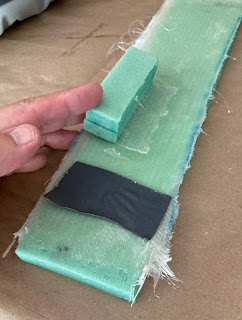
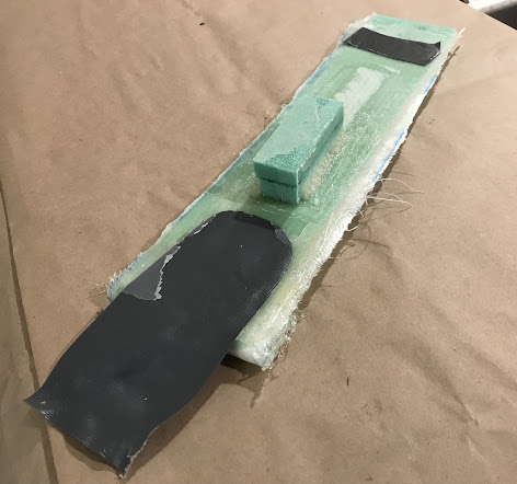
I wanted to see if it was possible to bond the kayak’s vinyl fabric to the fiberglass and also find the best way to bond foam to foam (simulating the bilge keel connection). I first tried some vinyl cement I found on Amazon that had good reviews. The foam to foam bond was weak (as expected) but the vinyl to fiberglass bond wasn’t bad; the material failed before the bond during a shear test, but the adhesion was just not strong enough for such a critical bond during the “peel test”.
Next I tried priming the vinyl with the cement, letting it sit a couple minutes and then applying the epoxy resin to both surfaces before bonding. While I let that set over night, I started making mold templates and calculating the bending radius, circumference and area of each frame template.
I will use these to cut out plywood frames that get mounted vertically to a 2x4 mini-strongback . They’ll be eight frames spaced every 10 inches and foam will get laid on top of these and screwed along the perimeter to create the desired hull shape with some help from the heat gun.
My second test layup turned out much better. Using epoxy resin as the bonding agent and pre-wetting the vinyl with vinyl cement produced very strong bonds for both the foam-to-foam and foam-to-vinyl connections:
Here are the two problems I encountered:
—In order to achieve this bond, I had to apply static pressure to both sides of the bond while it cured overnight. With a flat surface it was easy to do by laying the laminate down on the counter then placing peel-ply, plastic wrap and some books on top. I don’t see a way of doing this with my proposed vinyl-to-fiberglass joint; it’s a compound curve and there’s no way of getting behind the fiberglass hull to apply opposing pressure. I considered using very long pop rivets or even clecoes to mechanically attach the two surfaces together but I’m almost certain at least one of the holes would leak. I would also worry the fiberglass would not be strong enough to resist the pressure of the rivet’s formed head; some might very well pull through during installation. Vacuum bagging might also work, but that was a bridge-too-far for this shade-tree fabricator.
—The other problem was that the vinyl would start curling and contracting as soon as the PVC cement was applied, making it challenging to get the epoxy on fast enough to get the layup laid flat and compressed. I was able to work fast enough with the small test layup to get a satisfactory bond, but the hull would be much more challenging since the perimeter of the bond is much longer, AND it’s circular & continuous so you can’t break it up into separate layups. I just don’t think I could work fast enough, even with a second set of hands.
Until I can resolve these issues, I’ll just have to be content with my inflatable kayak, and accept the fact that an annual replacement will likely be necessary as the vinyl underside gets torn or punctured.
———————————————
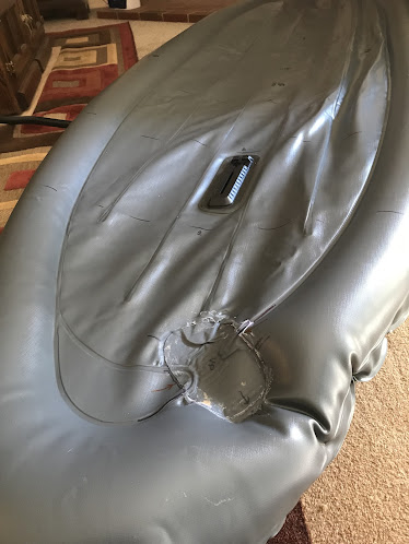
After stewing over this for a couple days, a closer inspection of the kayak revealed that the bottom air chamber was actually comprised of two bladders, upper and lower, connected by a narrow passageway:
The upper bladder inflates the lower perimeter of the hull and provides most of the buoyancy. The lower bladder inflates the relatively flat floor of the kayak that you actually sit on; it contributes minimally to the kayak’s buoyancy. If I could isolate these two bladders, I could inflate the upper while leaving the lower uninflated; this would give me a much more accommodating surface to bond a hard fiberglass shell to. The fiberglass “hull” would need to be flat (no curvature) so it wouldn’t provide any additional displacement (and no additional buoyancy, aside from the volume of the foam itself) but the kayak could now have the desired bottom protection and improved tracking ability. It would now be possible to apply a constant pressure to the joint overnight, greatly increasing the chance of a solid bond. As an added bonus, I’d sit a bit lower in the water, increasing stability. This is the path I chose to follow. Will it work? Let’s find out!
I created a spacer to ensure solid pressure on the passageway while the vinyl cement cured.
Then I cut a slit in the layer of vinyl that comprised the bottom layer of the bottom air chamber; it had to be large enough to insert the applicator for the vinyl cement but small enough to easily patch once the cement had been applied. Working quickly, I globbed in a bunch of vinyl cement between the two layers of the bottom air chamber at the passageway connection point, applied more vinyl cement on the outside of chamber, laid on a precut vinyl patch and the spacer, then compressed everything together using books and a heavy toolbox.
After letting it cure overnight, I removed the books and spacer to inspect my handiwork; the joint appeared to be solid. I pumped up the bottom air chamber and the joint held; the upper bladder inflated and the lower bladder remained uninflated. I now have a static, flexible, relatively flat surface that I can get a backing plate behind, which (hopefully) allow me to bond the solid keelpiece to the flexible vinyl bottom of the kayak.
I then began fabricating my hull piece by cutting foam to create the bottom pan and two miniature bilge keels; they got bonded together using epoxy resin mixed with adhesive filler:
Since I had some older polyester resin that was nearing the end of its shelf life, I used that and some 1708 glass cloth to laminate the underside of the hull pan. I then glassed over the bilge-to-hull joints using epoxy resin (NOTE: epoxy will bond to polyester, but polyester is unlikely to bond with epoxy…see HERE). Next, I fiberglassed the curved ends using some 4 ounce biaxial cloth and lastly used 6 ounce cloth to fiberglass the foam keels to the foam bottom pan. I used epoxy resin throughout and peel ply on top of the fiberglass cloth to create a nice uniform, lightly textured surface.
I then fabricated the temporary backing plate; it needed to be a bit larger than the GRP hull piece but still small enough to insert into the top opening of the kayak. I decided to cut it in half and attach supports that could be unscrewed. Here’s the backside of the backing plate before insertion:
I then disassembled the backing plate, slid each half into the kayak separately and then reassembled:
I could then flip the kayak over, place the keel piece on the underside of the hull (centered on the pre-marked CG location) with the backing plate positioned internally to provide a solid surface below the keelpiece; it’s finally ready for bonding!
I chose a cool day to give the epoxy some extra working time, got everything set up and started the bonding process. I first slathered epoxy cement on the underside of the vinyl hull and while that was setting, mixed up my first batch of epoxy resin; this got brushed over the PVC foam of the keelpiece. I mixed another batch of epoxy, added some structural filler to thicken it up, quickly went back and touched up the vinyl with some more cement, troweled on the epoxy filler, then carefully laid the pre-wetted keel piece onto the premarked vinyl underside. Lastly, I compressed everything as best I could and let it cure overnight. This was a pretty big layup (at least for me), so I didn’t have time to take many pictures, but here’s the final assembly while it cured:
Here is the final assembly, showing the keelpiece bonded to the underside of the cockpit, the upper bladder inflated, and the air block keeping the lower bladder uninflated:
Here’s a picture looking aft at the keelpiece showing the twin keels which will hopefully improve tracking ability, and allow a stable beaching platform while at the same time protecting the vinyl underside of the kayak:
Once deflated, it easily folds into thirds and results in a tidy package measuring ≈ 42” x 18” and weighing ≈ 22 pounds; certainly much easier to store below decks than a RIB or a hard shell kayak!


